

Marjan Polymer Industries supplies and configures 3D Printer systems in Pakistan for product development, engineering prototypes, jigs, fixtures, educational work, tooling and low-volume thermoplastic parts. The principal scope is material-extrusion equipment commonly described in the market as FDM or FFF filament 3D printing.
Selection is based on build volume, part material, dimensional requirement, layer strategy, nozzle and extrusion system, bed and chamber temperature, support method, production duty, software workflow and operator capability. MPI defines the printer, material handling, safety, training and acceptance test around the intended application.
Additive Manufacturing by Material Extrusion
Additive manufacturing builds a three-dimensional geometry from digital model data through successive addition of material. In an FFF workflow, thermoplastic filament is driven into a heated nozzle, deposited along a sliced toolpath and bonded layer by layer on the build platform.
Part performance is affected by geometry, layer direction, raster, wall count, infill, temperature, cooling, moisture, support and post-processing. A printer specification alone does not establish the strength or certification of a finished component.
Available 3D Printer Configurations
| Configuration | Typical Use | Available Design Approach |
|---|---|---|
| Open desktop FFF printer | PLA models, education and basic prototyping | Compact single-extrusion system with accessible build area |
| Enclosed professional printer | ABS, ASA, PETG, engineering prototypes and small fixtures | Rigid frame, enclosure, filtered airflow and controlled build platform |
| Dual-material printer | Soluble or breakaway support and multi-material development | Independent or paired extrusion architecture with compatible materials |
| High-temperature FFF system | Nylon, PC and selected reinforced or high-performance polymers | Application-rated hotend, heated chamber, bed and dry material path |
| Large-format industrial printer | Large prototypes, patterns, tooling and production aids | Extended build volume with thermal, motion and process controls |
| Custom research platform | Polymer, composite and process-development studies | Open parameter access, sensors and project-specific extrusion options |
Applications in Pakistan
- Concept models and rapid engineering prototypes
- Assembly jigs, drill guides, fixtures and inspection aids
- Patterns, mould masters and vacuum-forming tools
- Low-volume customized covers, brackets and non-critical components
- Architecture, product design and presentation models
- University teaching, research and laboratory method development
- Automotive, textile, polymer and industrial maintenance prototypes
- Anatomical, medical-training or assistive models where regulatory use is not implied
- Composite lay-up aids and removable cores using approved materials
- Spare-part evaluation before conventional manufacture
Reference Printer Concept
The current MPI listing records a dual-extrusion FFF concept with an approximately 300 × 250 × 300 mm build envelope, nominal 0.4 mm nozzles, a stated high-temperature hotend target and a touchscreen interface. These values are retained as a reference category and require model confirmation before quotation.
| Reference Parameter | Recorded Concept | Contract Note |
|---|---|---|
| Process | Fused-filament material extrusion | Actual machine process and licence terminology are stated in the offer |
| Build envelope | Approximately 300 × 250 × 300 mm | Usable space can reduce with dual extrusion, purge or fixtures |
| Extrusion | Dual-nozzle reference | Independent, switching or single-head architecture is model-specific |
| Nozzle | Nominal 0.4 mm reference | Other diameters and wear-resistant materials may be available |
| Layer setting | Fine layers previously stated to approximately 0.04 mm | Validated layer height depends on nozzle, material and geometry |
| Hotend temperature | Reference claim up to approximately 350 °C | Continuous rating and material compatibility require datasheet approval |
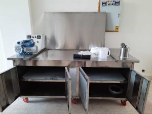
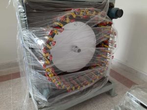
Specification control: product photos and recorded values identify a reference concept. The selected model datasheet, signed quotation, acceptance protocol and serial-number documentation govern supply.
Configurable Technical Scope
| Parameter | Available Selection | Defined From |
|---|---|---|
| Build volume | Desktop, professional and large-format ranges | Largest part, orientation and support space |
| Extruder | Single, dual, independent dual or project-specific | Model material, support and productivity |
| Nozzle system | Standard, hardened, wear-resistant or high-temperature | Polymer, filler, temperature and nozzle diameter |
| Build platform | Heated removable plate with material-specific surface | Adhesion, release, flatness and operating temperature |
| Chamber | Open, enclosed or actively heated | Warp risk, polymer class and part size |
| Motion | Cartesian, CoreXY or selected industrial architecture | Envelope, speed, rigidity and serviceability |
| Controls | Local touchscreen, network and monitored workflow | Production policy, cybersecurity and traceability |
| Accessories | Dryer, storage, extraction, support-removal and tools | Material handling and application workflow |
Build Volume and Usable Workspace
Build volume should be selected from the largest part after orientation, brim, support, purge structure and collision clearances are considered. A nominal envelope is not always fully usable with every toolhead or material combination.
Large parts increase thermal contraction, build time and failure exposure. Splitting and joining a design can sometimes be more economical than selecting a substantially larger machine.
Motion System, Resolution and Accuracy
Axis step size or software resolution is not the same as finished-part accuracy. Frame rigidity, belt or screw condition, backlash, calibration, material shrinkage, layer height and slicing strategy all affect dimensions.
Acceptance should use a defined artifact, material, orientation and measurement method. Dimensional tolerance must be agreed for the intended feature range instead of applying one figure to every geometry.
Nozzle Diameter and Layer Height
A smaller nozzle can produce finer features but generally reduces deposition rate and increases blockage sensitivity. A larger nozzle improves throughput and bead strength but limits fine walls and small text.
Layer height is normally selected as a practical fraction of nozzle diameter. Very thin layers increase build time and do not automatically improve dimensions if motion, extrusion or material control is unstable.
Single and Dual Extrusion
Single extrusion is simple and efficient for one model material with breakaway supports. Dual-material systems can add soluble support, a second colour or a second compatible polymer, but introduce alignment, purge, contamination and inactive-nozzle considerations.
Support compatibility must be checked with the model material and chamber temperature. Soluble supports may require a controlled removal bath and approved chemical or water-handling procedure.
Material Compatibility
| Material Family | Typical Use | Machine Requirement |
|---|---|---|
| PLA | Models, education and visual prototypes | Basic hotend and controlled cooling |
| PETG | Durable prototypes and general fixtures | Stable extrusion and suitable build surface |
| ABS / ASA | Functional prototypes and outdoor-capable parts | Enclosure, heated bed and ventilation |
| TPU / flexible filament | Gaskets, grips and compliant parts | Short constrained feed path and tuned speed |
| Nylon / polyamide | Wear-resistant functional parts | Dry material, suitable hotend and controlled chamber |
| Fibre-filled polymer | Stiffer tooling and engineering components | Wear-resistant nozzle and validated feed system |
| PC and high-temperature polymers | Demanding engineering applications | Model-specific hotend, bed, chamber and safety provisions |
Reinforced and Abrasive Filaments
Carbon- or glass-filled filaments can improve stiffness and dimensional behaviour but are abrasive and can rapidly wear a soft brass nozzle. A hardened or otherwise wear-resistant nozzle and compatible feeder are normally required.
A filled filament is not equivalent to continuous-fibre composite reinforcement. Mechanical properties remain anisotropic and depend on fibre content, orientation, porosity, moisture and print settings.
Filament Diameter and Feed Control
Common contemporary systems use a defined filament diameter such as 1.75 mm, while some industrial or legacy platforms use other sizes. Printer, feeder, hotend and slicer settings must all match the actual filament.
Diameter tolerance, ovality, spool winding and friction influence flow stability. MPI does not retain the earlier generic 3.0 mm statement as a universal requirement; the selected model determines feedstock size.
Heated Bed, Enclosure and Chamber
A heated bed supports first-layer adhesion and reduces thermal gradients. An enclosure protects the build from drafts and can retain heat. An actively heated chamber provides tighter thermal control for demanding polymers and larger parts.
Maximum hotend temperature alone does not prove high-temperature material capability. The feeder, heat break, chamber, bed, sensors, firmware and electrical safety must be rated for the full process.
Support Material and Complex Geometry
Supports provide a foundation for overhangs, bridges and internal geometry. Breakaway support is removed manually; compatible soluble support can reduce labour for inaccessible cavities and complex assemblies.
Support interface, orientation and removal process influence surface quality. Designers should balance geometric freedom with cleaning access, trapped solution, dimensional risk and post-processing time.
Slicing, File Preparation and Workflow
The workflow normally moves from a validated CAD model to a mesh or supported 3D format, repair and orientation, slicing, toolpath review, build transfer, printing, removal, post-processing and inspection. File units and geometry integrity should be checked before slicing.
Open or vendor software may control walls, infill, support, temperatures, speeds, cooling and machine code. Software name and version are confirmed for the selected printer; unsupported legacy software is not presented as a current universal solution.
Connectivity and Data Management
Depending on model, files may transfer by removable media, USB, local network, cloud or managed print software. Industrial and institutional users should define account control, update policy, backups, network isolation and intellectual-property protection.
Remote cameras, job queues and notifications can improve supervision but do not replace safe operating procedures. Unattended operation is permitted only within the machine manufacturer’s documented conditions and site risk assessment.
Print Quality and Process Variables
| Observation | Likely Variables | Check |
|---|---|---|
| Poor first-layer adhesion | Bed level, surface, temperature or contamination | Calibration, cleaning, offset and material profile |
| Warping | Thermal gradient, material shrinkage or part geometry | Enclosure, bed, chamber, brim and orientation |
| Under-extrusion | Moisture, blockage, feeder slip or wrong flow data | Drying, nozzle, drive path and slicer profile |
| Stringing | Temperature, retraction, travel or wet filament | Material profile, drying and toolpath |
| Layer shift | Mechanical slip, collision or excessive acceleration | Belts, pulleys, motion and part clearance |
| Dimensional error | Shrinkage, flow, orientation or compensation | Calibration artifact and material-specific settings |
Productivity and Build Economics
Build time depends on layer height, nozzle, speed, acceleration, material flow, supports, infill and part packing. Quoted maximum travel speed is not the same as stable deposition speed for a qualified part.
Total cost includes material, support, failed builds, labour, post-processing, energy, maintenance and machine utilization. MPI can compare a representative part rather than relying on a headline speed figure.
Filament Drying and Storage
Many engineering polymers absorb moisture, which can cause bubbles, weak bonding and poor surfaces during extrusion. Drying temperature and duration must follow the material supplier’s datasheet to avoid degradation or spool damage.
Dry boxes, sealed containers and humidity indicators can be included. Material should be identified by grade, colour, lot and drying history where repeatability matters.
Ventilation and Operator Safety
- Use an enclosure and ventilation approach appropriate to the polymer and site.
- Prevent contact with hot nozzles, bed, chamber and recently printed parts.
- Keep guards and interlocks functional; isolate power before maintenance.
- Control moving-axis pinch points and unexpected automatic motion.
- Review material SDS, emissions, dust and post-processing chemicals.
- Provide fire detection and operating supervision according to risk assessment.
- Do not print materials outside the model’s approved temperature and ventilation range.
Maintenance and Calibration
Routine work can include bed cleaning, nozzle inspection, feeder cleaning, lubrication where specified, belt or screw checks, fan and filter service, firmware management and electrical inspection. Abrasive materials shorten nozzle life.
Calibration may cover bed mesh, Z offset, extrusion flow, temperature, dual-head alignment and dimensional compensation. A controlled reference build helps verify the machine after service or material change.
Power and Installation Planning
Electrical demand depends on hotend count, bed, chamber, size and accessories. The selected model is checked for Pakistani supply voltage, earthing, surge protection and any recommended UPS or power-conditioning arrangement.
Site planning should include a stable bench or floor, ventilation, clearance, network policy, dry material storage, post-processing space and safe waste disposal. Ambient temperature and dust can influence reliability.
Factory and Site Acceptance
Acceptance should define the printer configuration, material, nozzle, build file, layer profile, completion criteria and measurements. A benchmark part can include holes, walls, overhangs and dimensional features relevant to the customer.
Cosmetic models, functional fixtures and certified end-use parts require different criteria. Mechanical, flame, biocompatibility or aerospace compliance is not implied unless supported by specified material, process and testing records.
Information Required for Selection
| Customer Input | Required Detail |
|---|---|
| Parts | CAD files, largest dimensions, features and expected tolerances |
| Material | Polymer grade, reinforcement, colour and certification needs |
| Purpose | Visual model, prototype, tool, fixture or end-use component |
| Output | Parts per week, build duration and operating shifts |
| Support | Breakaway, soluble or same-material strategy |
| Site | Power, ventilation, network, space and operator skill |
| Quality | Dimensional, surface and mechanical acceptance criteria |
| Delivery | Location, training and commissioning requirement in Pakistan |
Installation, Training and Support in Pakistan
MPI can support supply, installation, calibration, benchmark printing and operator training in Lahore, Karachi, Faisalabad, Islamabad and other Pakistani locations. Scope depends on machine class, accessories and application.
Training can cover safe startup, material loading, drying, slicing, bed preparation, build monitoring, removal, routine maintenance and troubleshooting. Application development and certified-part qualification are quoted separately.
Important Performance Limitations
Layered thermoplastic parts are direction-dependent and can contain voids or weak interfaces. Strength, heat resistance, chemical resistance and dimensional stability depend on material, build orientation, process and post-treatment.
Reference photographs and specifications do not promise a particular brand or model. Final build volume, temperatures, speed, accuracy, software, accessories, warranty and material list are controlled by the selected-model quotation.
Why Configure the Complete Printing Workflow
A successful installation combines printer, feedstock, dryer, build surface, software, ventilation, post-processing, measurement and trained operators. Buying only by nozzle temperature or nominal build volume can leave essential workflow gaps.
MPI uses customer parts and materials to define a supportable package for Pakistan, with clear acceptance criteria and realistic application boundaries.
Frequently Asked Questions
What type of 3D printer does MPI supply?
The main scope is filament material-extrusion equipment commonly called FDM or FFF, from desktop prototyping to enclosed and industrial systems.
What build volume should I choose?
Select from the largest oriented part plus support, brim, purge and clearance. A nominal volume may not be fully usable with every toolhead.
Can the printer use carbon-fibre filament?
Selected fibre-filled filaments can be used when the feeder, hotend and wear-resistant nozzle are compatible. This is not the same as continuous-fibre reinforcement.
Is dual extrusion necessary?
It is useful for soluble support or two compatible materials, but adds alignment and purge complexity. Single extrusion is often more efficient for simple work.
Can I print ABS and nylon?
Yes on a model with the required enclosure, bed, chamber, hotend and material-drying controls. Exact grade compatibility must be checked.
Does a 350 °C nozzle mean every engineering polymer is supported?
No. The full hotend, feeder, chamber, bed, firmware and safety system must be rated, and the material must appear in the selected model’s approved list.
What determines 3D printed part accuracy?
Machine calibration, material shrinkage, geometry, orientation, layer profile, extrusion and measurement method all contribute. Resolution alone is not accuracy.
Can printed parts replace machined parts?
Sometimes for prototypes, tools and appropriate low-volume components, but material properties, anisotropy, tolerances and application risk must be evaluated.
What is needed for a quotation?
Share CAD files, largest part, material, purpose, tolerance, output, support requirement, site utilities and delivery location in Pakistan.
Does MPI provide training in Pakistan?
Installation, calibration, benchmark printing and operator training can be included according to the selected printer and project scope.