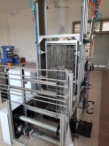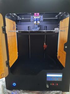


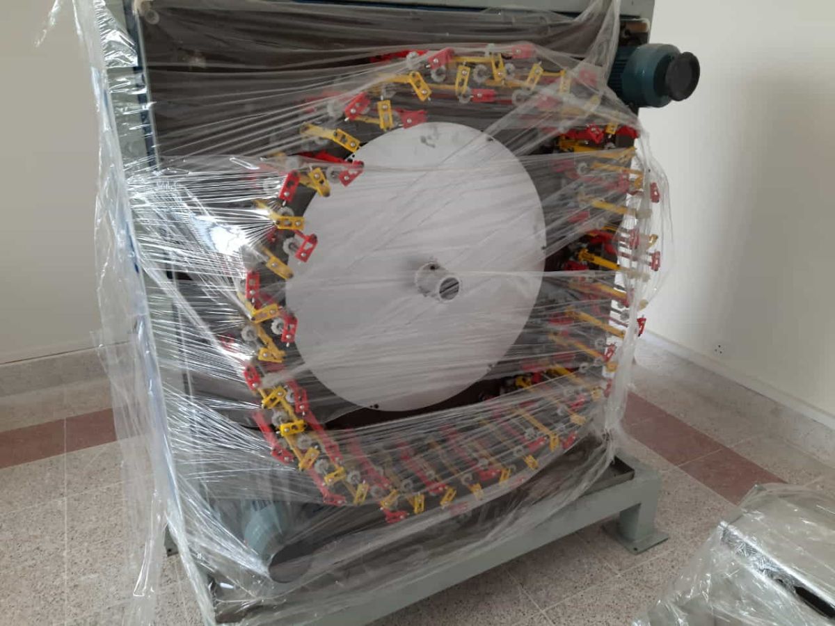
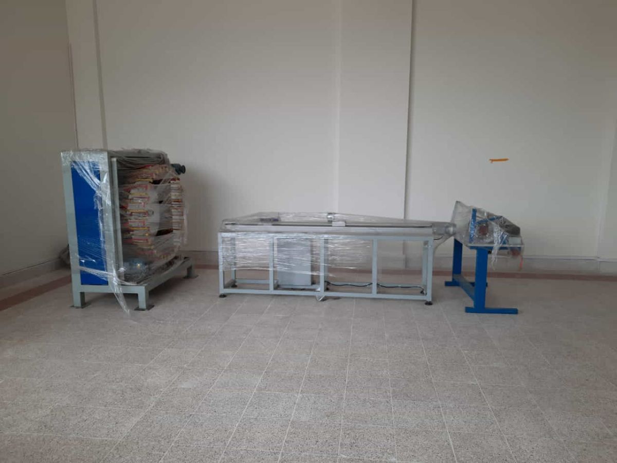
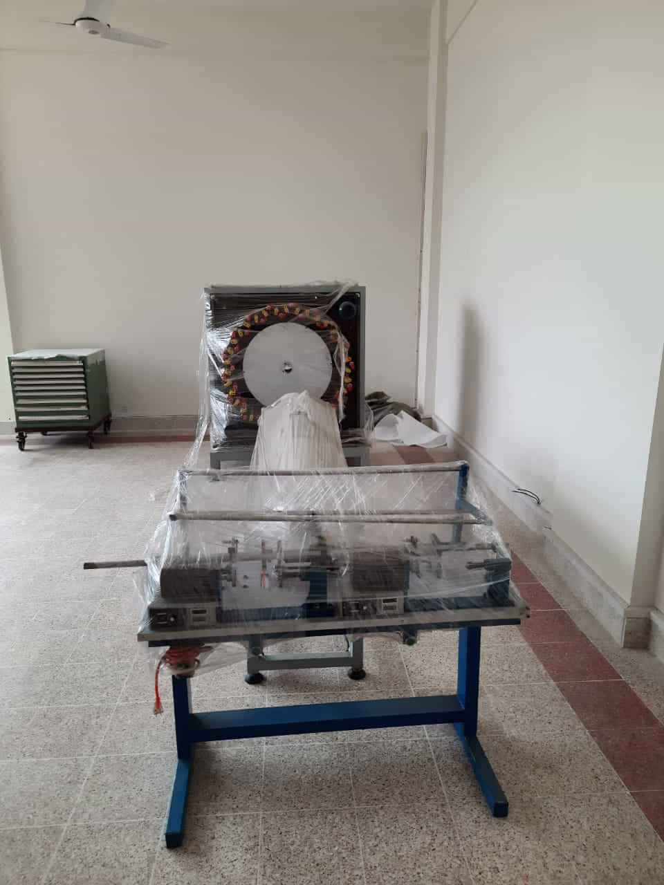
Marjan Polymer Industries supplies and engineers Braiding Machine systems in Pakistan for producing round, flat, tubular, square and overbraided structures. Applications can include rope, cord, cable covering, hose reinforcement, protective sleeving, gland packing and composite preforms using textile yarns, technical fibres or approved fine wire.
A braider is selected around product geometry, finished diameter, carrier count, material package, braid angle, cover factor, tension, core or mandrel, production speed and downstream take-up. MPI defines the machine, bobbin-winding method, payoff, haul-off, controls and guarding as one project rather than quoting an unsupported carrier count alone.
Braiding Technology for Industrial Production
In a conventional maypole process, yarn carriers travel on interlacing paths while material is drawn through the braiding point. The relationship between carrier speed and linear take-up establishes lay length and braid angle. Stable tension and consistent bobbin winding are essential for uniform coverage.
Radial and application-specific systems can arrange carriers around a central product or mandrel. The correct architecture depends on whether the required product is a simple cord, a core-covered rope, a high-pressure hose reinforcement, an electrical shield or a near-net-shape composite preform.
Available Braiding Machine Configurations
| Machine Type | Typical Products | Available Design Approach |
|---|---|---|
| Round braiding machine | Cord, rope, cable cover, hose and tubular sleeve | Maypole carrier arrangement with central core path and controlled take-up |
| Flat braiding machine | Tape, lace, wick, narrow trim and flat technical braid | Track geometry and take-off matched to required width and edge formation |
| Square or packing braider | Gland packing, sealing braid and dense square sections | Multi-track arrangement with optional impregnation and vertical discharge |
| Wire braiding machine | Hose reinforcement, cable shielding and protective metallic braid | Wire-compatible carriers, bobbins, tension, lubrication and take-up |
| Radial composite braider | Carbon, glass, aramid and hybrid-fibre preforms | Radial carriers with mandrel handling and recipe-controlled coordination |
| Harness or overbraiding machine | Cable bundles, wiring harnesses and shaped cores | Guided product feed with contour-capable take-off or robotic handling |
Applications in Pakistan
- Industrial and commercial rope, cord and shock-cord production
- Hydraulic and pneumatic hose reinforcement
- Electrical cable shielding, insulation overbraiding and harness protection
- Textile sleeving, laces, wicks, sash cord and narrow technical products
- Gland packing for pumps, valves and rotating equipment
- Glass-fibre insulation braid and high-temperature technical sleeves
- Carbon, glass, aramid and natural-fibre composite preforms
- Medical or fine technical braids where validated materials and clean production are specified
- Marine, safety, sporting and load-related ropes subject to product standards
- Research, university laboratories and product-development facilities
Reference Product Concept
The existing MPI reference listing describes a horizontal, single-head industrial concept for carbon, glass, jute and related technical yarns, with an indicated configuration around 56 carriers and adjustable take-up. That information is treated as a project starting point, not a universal guaranteed specification.
| Reference Parameter | Recorded Concept | Contract Note |
|---|---|---|
| Machine orientation | Horizontal braiding arrangement | Vertical, horizontal or radial layout is selected from product handling |
| Carrier scale | Approximately 56-carrier reference concept | Carrier count, tracks and bobbin quantity require drawing confirmation |
| Material family | Carbon, glass, jute and compatible yarns | Actual tow, yarn, wire or tape must be trialled |
| Product diameter | Reference window previously stated around 3–20 mm | Achievable diameter depends on carrier count, yarn build and braid angle |
| Drive | Inverter-controlled electric drive concept | Motor, supply and speed are finalized from load and production target |
| End monitoring | Yarn-break stop indicated | Sensor technology depends on material and carrier configuration |
Specification control: the signed quotation, approved general-arrangement drawing, material trial, datasheet and machine nameplate govern the supplied system.
Configurable Technical Scope
| Parameter | Available Selection | Defined From |
|---|---|---|
| Carrier count | Compact to high-carrier engineered configurations | Product diameter, yarn count, braid pattern and output |
| Machine orientation | Vertical, horizontal, radial or product-specific | Core handling, floor space and take-up route |
| Material | Textile yarn, glass, carbon, aramid, natural fibre or approved wire | Linear density, stiffness, abrasion and tension sensitivity |
| Braid geometry | Round, flat, square, tubular, biaxial or triaxial | Product drawing and performance requirement |
| Core / mandrel | None, flexible core, hose, cable, tube or rigid preform mandrel | Internal construction and overbraiding process |
| Take-up | Capstan, belt, caterpillar, drum or robotic system | Diameter, stiffness, speed and product path |
| Controls | Inverter, PLC/HMI, recipe and synchronized servo functions | Repeatability, changeover and automation level |
| Utilities | Project-specific electrical and pneumatic services | Machine load, controls and plant standard |
Carrier Count and Track Selection
Carrier count influences strand count, coverage, product diameter and achievable pattern. Common industrial machines can range from a small number of carriers for simple cords to dozens or more for large sleeves, wire reinforcement or composite preforms.
More carriers do not automatically increase quality. Track pitch, horn-gear geometry, bobbin capacity, yarn width, carrier tension and braiding-point stability must be balanced. Carrier quantity is finalized from a product construction sheet.
Round, Flat and Square Braid Geometry
Round braids are produced around a centre line and may be hollow or built over a core. Flat braids use track geometry and take-off that forms a tape-like section. Square packing machines create dense multi-track sections used for sealing and insulation.
The required cross-section, edge quality, number of interlacings and compression behaviour should be defined with samples or a drawing. Changing only the guide at the convergence point cannot convert every machine between these geometries.
Biaxial and Triaxial Composite Preforms
A biaxial braid uses two interlacing yarn directions. A triaxial construction adds longitudinal or axial yarns to improve stiffness and dimensional stability along the product direction. Composite preform selection depends on load path, resin process and final component geometry.
Carbon, glass, aramid and hybrid yarns can require low-friction guides, large bend radii, controlled tension and dust management. Tow spreading, fuzz generation, mandrel contour and fibre-volume targets should be evaluated in development trials.
Braid Angle, Pitch and Coverage
Braid angle is controlled primarily by the ratio of carrier motion to linear take-up. Slower take-up relative to carrier rotation generally increases braid angle and coverage; faster take-up reduces the angle. Actual behaviour also depends on product diameter and material.
Recipes should record carrier or horn-gear speed, take-up speed, die or ring position, core diameter, yarn count and tension. A sample approved at one diameter cannot be assumed to retain its angle after a core or speed change.
Yarn, Fibre and Wire Compatibility
| Material Family | Engineering Consideration | Possible Machine Provision |
|---|---|---|
| Polyester, nylon and polypropylene | Stretch, heat, friction and package stability | Textile carriers, controlled tension and standard guides |
| Aramid | Low elongation, abrasion sensitivity and cutting | Smooth wear parts, suitable guides and stable low tension |
| Glass fibre | Filament damage, dust and bend radius | Low-friction path, extraction and appropriate carrier package |
| Carbon fibre | Fuzz, conductivity, tow spreading and contamination | Conductive-dust controls, smooth guides and application trials |
| Natural fibre | Variability, hairiness and moisture | Open guides, cleaning access and adapted tension |
| Fine metal wire | Yielding, work hardening, lubrication and recoil | Wire carriers, robust bobbins, guards and controlled take-up |
Bobbin and Package Engineering
Bobbin capacity sets the available running length between changes, while diameter and mass affect carrier dynamics. The bobbin must fit the carrier, contain the material safely and release it without snagging or damaging filaments.
Package geometry, traverse, flange condition and winding tension should be consistent across all carriers. Bobbins are matched components; dimensions from an unrelated machine should not be assumed interchangeable.
Bobbin Winding Requirements
Good braiding begins with uniform rewinding. Unequal package density or tension can cause carrier-to-carrier length differences, broken ends and visible pattern variation. A dedicated bobbin winder is commonly included or specified separately.
The winding system may provide length measurement, traverse control, tension setting, automatic stop and recipe management. The number of winding positions is selected from machine carrier count, bobbin capacity and required changeover time.
Tension Control and Yarn-Stop Monitoring
Carrier tension must remain stable as bobbin diameter decreases and the yarn path moves through the machine. Mechanical springs, weights, compensators or application-specific active systems can be used depending on material and sensitivity.
End-break sensors can stop the machine before a fault continues into the product. Transparent, conductive, fine or low-tension materials may need a tailored detection method and validation at production speed.
Core, Mandrel and Payoff Handling
Overbraiding requires the core, hose, cable or mandrel to enter the braiding point centrally and at a controlled rate. Flexible cores may use a payoff stand with braking or dancer control; rigid composite mandrels may require guided or robotic motion.
Core ovality, bending radius, fittings and diameter transitions can disturb the braid. Drawings should show the full part, including ends and maximum cross-section, not only the nominal diameter.
Take-Up and Product Collection
The take-up establishes linear speed and helps control braid angle. Capstan or wheel systems suit flexible products; belts and caterpillars can provide more contact; drums collect suitable continuous products; robotic handling serves complex preforms.
Traction must be sufficient without crushing, polishing or stretching the braid. Drum diameter, traverse and package mass are selected from product flexibility and required delivery length.
Controls, Recipes and Synchronization
A basic system may use inverter speed control and manual adjustment. More advanced machines coordinate braider, core payoff, take-up, winding and auxiliaries through PLC/HMI recipes, alarms and production counters.
Optional functions can include automatic ramping, break-stop logic, length stop, recipe access levels, trend display and communication with upstream or downstream equipment. Data availability is defined during controls engineering.
Production Speed and Output
Speed is limited by machine geometry, carrier mass, material, tension, product quality, noise, lubrication and take-up. Published industrial examples range widely; one radial high-carrier reference operates in an approximate 50–200 rpm window, while other braiders use different speeds and pitch sizes.
Contract output should be stated for a defined product construction, material package and acceptance criterion. Maximum unloaded speed is not a production guarantee.
Product Quality Control
| Quality Characteristic | Control Method | Typical Cause of Variation |
|---|---|---|
| Braid angle / lay length | Visual or dimensional measurement against recipe | Take-up ratio, diameter or speed change |
| Coverage | Image, mass or dimensional inspection | Carrier count, yarn width, tension or angle |
| Finished diameter | Non-damaging gauge at defined tension | Core size, material build or compaction |
| Pattern consistency | Repeat inspection across machine circumference | Misthreading, missing end or unequal bobbin tension |
| Surface damage | Visual inspection and material-specific test | Rough guides, excessive tension or tight bend radius |
| Length / package | Counter and final verification | Slippage, stretch or counter setup |
Changeover and Cleaning
Changeover includes safe stopping, bobbin replacement, rethreading, core setup, guide adjustment, recipe confirmation and first-piece approval. Quick-change carriers, clear threading diagrams and stored recipes can reduce downtime.
Carbon dust, glass fragments, lubricant, textile lint and wire debris require different cleaning controls. Material families should not be changed without reviewing contamination, extraction, electrical conductivity and operator protection.
Machine Safety and Guarding
- Interlocked guarding around moving carriers, horn gears and rotating assemblies
- Emergency stops accessible from operator and material-handling positions
- Safe speed, inching and setup modes where specified
- Protection at bobbin winding, payoff, capstan and take-up nip points
- Electrical isolation, overload protection and labelled control circuits
- Wire-recoil and fibre-dust controls appropriate to the processed material
- Risk assessment and operator procedures for the installed production line
Maintenance and Spares
Preventive maintenance typically covers track cleaning and lubrication, horn-gear inspection, carrier wear, guide condition, tension devices, belts, sensors, guarding and take-up alignment. The approved manual defines intervals and lubricants.
Recommended spares may include carrier wear parts, springs, guides, bobbins, sensors, belts, seals and electrical consumables. Critical part identification should be locked to the supplied machine serial number and drawing.
Utilities and Installation Planning
Foundation, floor loading, service access, electrical supply, compressed air, extraction and material routes are defined from the chosen system. A horizontal braider with payoff and take-up may require considerably more line length than its machine frame alone.
MPI confirms access doors, lifting route, operator envelope and maintenance clearance before dispatch. Pakistani voltage and site conditions are reviewed during electrical engineering.
Information Required for Engineering
| Customer Input | Required Detail |
|---|---|
| Finished product | Drawing, diameter or width, braid type and approved sample |
| Material | Fibre or wire type, linear density, strand count, coating and package |
| Construction | Carrier count, ends per carrier, core and target braid angle or coverage |
| Production | Required speed, shift pattern, lot length and changeover frequency |
| Core / mandrel | Dimensions, stiffness, transitions and payoff arrangement |
| Quality | Diameter, angle, coverage, tensile or application acceptance criteria |
| Site | Power, air, layout, floor, access and environmental controls |
| Compliance | Required guarding, documentation, testing and product standards |
Factory Testing and Acceptance
Where material is available, factory testing can verify threading, drive operation, carrier motion, safety functions, take-up synchronization and a defined sample braid. Customer-supplied production material is preferred because friction and package behaviour affect results.
An acceptance protocol should state the product recipe, operating duration, measurable characteristics and exclusions. Tensile, pressure, electrical or certified end-product performance testing is included only when specifically quoted.
Installation, Training and Support in Pakistan
MPI can support delivery, installation supervision, commissioning and operator training in Lahore, Karachi, Faisalabad, Sialkot, Islamabad and other Pakistani manufacturing centres. Scope is confirmed against machine complexity and site location.
Training can cover bobbin preparation, threading, carrier tension, recipe setup, first-piece inspection, fault response, changeover, cleaning and preventive maintenance. Production ownership then transfers through approved procedures and records.
Why Select a Project-Specific Braider
Braiding quality comes from coordinated machine geometry, carrier and bobbin design, tension, core control and take-up. A generic specification copied from another product can produce the wrong carrier count, diameter range or material path.
MPI develops the supply around the actual braid and provides a defined interface for winding, handling, controls and support. This makes the machine easier to evaluate commercially and technically before purchase.
Frequently Asked Questions
What products can a braiding machine make?
Depending on its design, a braider can produce rope, cord, flat braid, sleeve, hose reinforcement, cable cover, gland packing or composite preforms. One machine is not automatically suitable for all products.
How many carriers should I choose?
Carrier count depends on finished diameter, material, strand count, braid pattern and coverage. MPI calculates it from the product construction rather than selecting by maximum count.
Can one machine process carbon fibre and glass fibre?
It may be possible with suitable carriers, guides, tension and cleaning controls, but each tow and package should be trialled. Carbon conductivity and glass abrasion require specific precautions.
What controls the braid angle?
The main control is the ratio between carrier motion and linear take-up, together with product diameter. Recipes coordinate these values to reproduce the approved structure.
Can the machine braid over a hose or cable?
Yes, when configured as an overbraider with compatible core payoff, centre guidance, braiding ring and take-up. Core diameter, stiffness and fittings must be provided.
Is a bobbin winding machine required?
Consistent winding is strongly recommended because package density and tension affect breaks and braid uniformity. MPI can include a compatible winder in the project.
Can MPI supply a wire braiding machine?
Yes, subject to wire diameter, alloy, tensile condition, bobbin, lubrication, carrier and safety review. Textile carriers should not be assumed suitable for wire.
What production speed can be guaranteed?
Output is guaranteed only for a defined product, material and acceptance test. Maximum machine rpm alone does not establish metres per hour or quality.
What details are needed for a quotation?
Share product drawing and sample, material and package data, construction, diameter, braid angle or coverage, output target, core details, utilities and delivery location.
Does MPI provide installation in Pakistan?
Installation supervision, commissioning, training and spare-parts planning can be included for Pakistani sites according to the quoted project scope.